Step 6 Metalwork: floorchannel, frame and door unit, top plate
The dimensions of the floorchannel and the frame and door unit assume a core with outside dimensions of 220 x 348 x 537 mm. If these dimensions differ you need to adapt the figures.
There's 3D SketchUp files for the floorchannel, and for the door/frame unit. There’s also a 2D pdf-file that you can print.
Making the frame and door
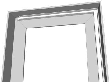
Frame
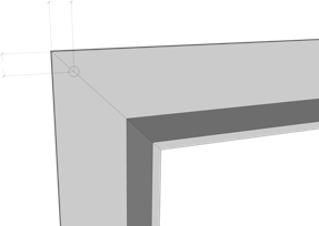
You need L-profile of 40 x 40 x 4 mm for the frame. Cut the 45º angles according to Figure 2 and weld the parts together. Four Ø 5 mm holes are drilled at the outer corners at 10 mm from the edges (fig 3).
Making the floorchannel
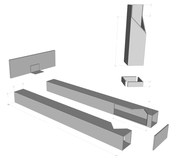
From a 30 x 30 x 2 mm square tube, cut two
330 mm pieces, a 110 mm piece, and a 10 mm edge. A triangle of 26 x 26 x 37 mm is cut out of the two long pieces, at 10 mm from the end. A slot of 26 x 85 mm is also ground away. The two pieces are now welded together according to the drawing (fig 1).
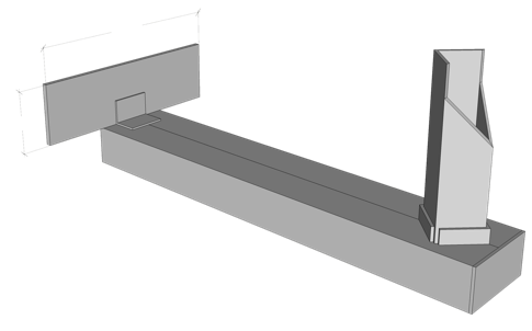
Cut the 10 mm edge diagonally in half and weld it around the square opening, ensuring the 30 x 30 x 110 mm tube fits snugly inside.
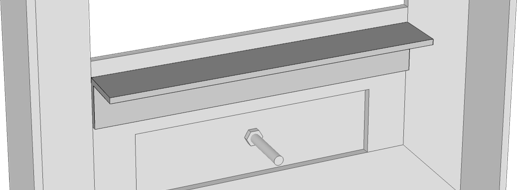
On this 110 mm piece, starting diagonally 20 mm below the top, draw two 45º angles. Cut out the angles plus the 20 mm (see the drawing). This tube (the "stub") is placed in the holder and is not welded. It will need to be replaced periodically, unless it is made of a special heat-resistant sort of steel called RA253MA.
A plate of 158 x 48 x 4 mm is welded with an angle iron to the front end.
At the other end you weld a closing plate of 60 x 30 x 2 mm.
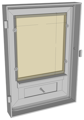
The door
Also for the door you use 40 x 40 x 4 mm L-profile.
Cut and weld according to Figure 4.
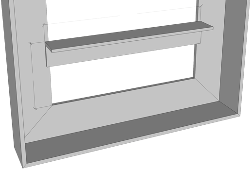
On the inside, at a height of 68 mm, weld a length of 175 mm from a 25 x 25 x 3 mm L-profile (fig 5). This will support the window. It also ensures that the air vent plate does not warp during welding.
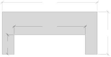
An air gap of 126 x 35 mm is cut out from a plate of 168 x 76 x 4 mm. This plate is then welded into the door (fig 6).
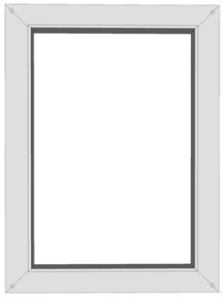
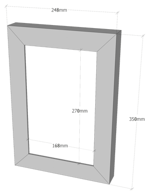
2. Frame dimensions
3. Location of the holes
4. Door dimensions
U-profile of 10 x 10 x 1.5 mm will now be placed on the inside of the door (fig 7). A corner of 15 x 6 mm is ground off on the hinge side of the two shorter pieces. They are welded tightly against the top and bottom. The profile on the side where the closure will be placed is fixed at a distance of 3 mm from the side. After assembly, the edges of the frame must fit exactly in this. There will be no U-profile on the hinge side, there will only be glass tape of 3 x 12 mm.
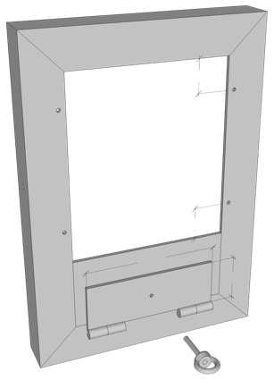
Figure 8 shows four 4mm holes, drilled 35mm from the top and bottom and 8mm from the side. This is where the bolts will come in that hold the window in place.
You can also see the 144 x 50 x 4 mm valve that closes the air opening. Exactly in the middle you drill a hole of Ø 5 mm, through which a bolt goes on which an eye nut is attached.
Clamp the plate in place and weld the hinges. The valve can only be opened completely (the bolt then bounces against the edge) and closed completely.
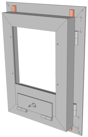
Assembling
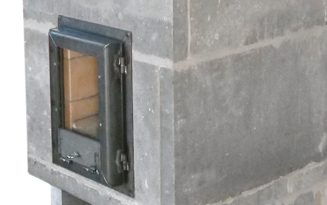
The hinges are now welded on: on the door this is 40 mm from the top and bottom (fig 10). Place the frame on a flat table and place four 8 mm blocks on top. You place the door on the blocks; the door now “floats”
8 mm above the frame. Move the door in such a way that the space between the frame and the door is
6 mm on the side where the lock comes (see image above). The edges of the frame then fit exactly into the U-profile. Hold it in place with a few clamps.
Weld the hinges to the frame and door.
10. The welded-on hinges
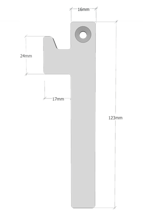
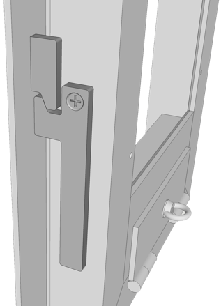
11. Lock
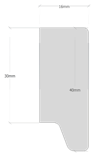
Figure 11 shows the lock. The lock and the lip that accepts the grip are cut from a 6 mm thick steel plate (fig 12). You weld that lip onto the frame, the top 160 mm below the frame edge and the left side 15 mm from the edge.
Now mount the door and place it on the 8 mm blocks on the closing side. Place the lock and determine the location where the hole will be (Ø 5 mm). You secure it with a bolt and two nuts.
Sealing
Press a 8 mm wide fire cord into the U-profile. At the window opening, glue strips of heat-resistant glass tape of 2 mm thick.
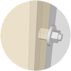
The window can now be placed.
Four stainless steel bolts of ± 20 mm hold the window in place. Two nuts ensure the correct distance (see picture).
12.
16
16
30
40
24
17
123

13. Fire cord and glass tape
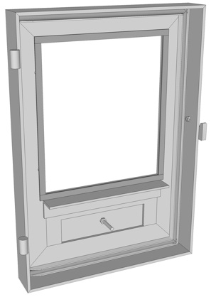
14. Window
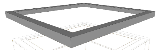
Top frame and top plate
Steel top frame
At the top of the bell is a frame made of 25 x 25 x 3 mm L-profile, to improve the sturdiness of the bell. The space between the bell and the frame is only 1mm, so it must be welded with care.
Dimensions are 608 x 608 mm on the outside, the square opening on the inside is 558 x 558 mm.
Top plate
The top of the bell is a 6 mm steel plate with dimensions 550 x 550 mm.

closing plate 60 x 30 x 2 mm


303
10
10


418


338

223

248
360
280
168

bolt with eye nut
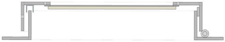
9. Cross-section of frame and door
6
3


2 hinges
± 10 x 40 mm


40
40


8
175
220

glass tape 2 mm


fire cord 8 mm


stub
1. Floorchannel
30
30

48
158
90
20
330
feed

10
10
30

holder
6. Air vent plate
7. U-profile
8. Holes, shut-off valve
5. L-profile 25 x 25 x 3


10
35
50
144


168
126
35
76
35