Building description (2019)
by Roelof Groenenboom and Steve Cassidy
In this description you can learn step-by-step how to make your own Roquetinho. All you need is some basic do-it-yourself skills, and for the metal work (someone with) welding skills. Materials costs will be less than
€ 200,-; if you build in series it can even be as low as € 125,- per stove (Portugal, 2018).
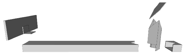
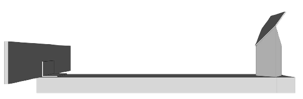
Roquetinho outline
Roquetinho is…
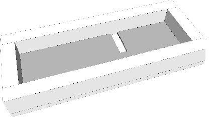
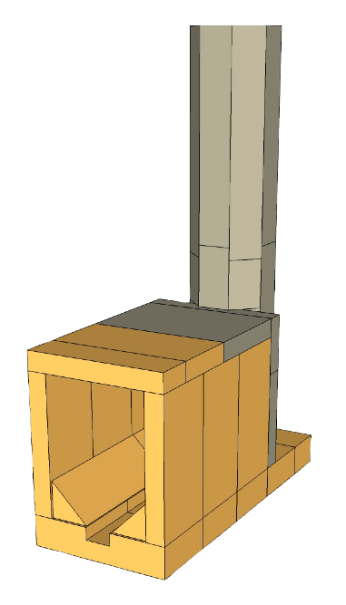
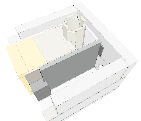
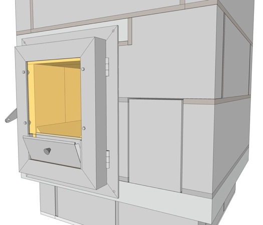
Structurally, the Roquetinho stove consists of a brickwork “bell” that absorbs and stores heat, within which is a rocket burner, consisting of a firebox and a riser to combust the hot gases. Firebox and riser together is called the “core”.
The bell consists of two parts: the lower part of concrete blocks and the upper part of firebricks. On top of the stove there’s a steel plate on which you can boil water.
Off-site prefabrication
This building description assumes that as much work as possible is done off-site, so as to minimise the time required on site. The preparatory (off-site) work consists of the following: making various special castings, building the first layer of the bell on the bottom slab, constructing the core, making the steel door, the floor channel, the top frame and top plate, and glueing the riser and the firebricks for the upper bell.
The first site work is construction of the plinth. The lower section of the bell is set on the plinth and the core fitted into the bell. Then the bell is completed on-site, before completion of the stove with the metalwork.
Archive
In the archive you can find older versions of the Roquetinho.
To accompany the building description of the former model there was a YouTube instruction video (building overview of the 2018 model).
And here’s the Sketchup file for the 2019 model, the one this description is about. The folder also contains seperate 3D files for the core, the floorchannel, the frame & door unit, and the moulds.
Step 1 Preliminary considerations, tools, materials
Before getting started with the stove it’s important to check a few things: the supporting floor needs to be strong enough, the chimney should be okay, and volume and insulation of the space to be heated should be in such a way the Roquetinho can do the job.
As much as possible the stove should be in the centre since it’s mainly a radiation heater. Further: the ventilation of the room has to be sufficient. There's no need for a separate air supply.
Foundation
A wooden floor does not have the strength needed to support the Roquetinho. A foundation is then a necessity. A connection with the nearest wall can be a solution. This works with a console (for example steel T-profiles inserted in the wall). Let only a professional do it!
Chimney
You need a chimney of at least 4 meter high, calculated from the stove bottom. Inside the room a singular inox tube of Ø 10 cm will do. Up from 30 cm under the ceiling and outside, the tube has to be double and insulated. Normal chimney rules are applicable such as having the top of the flue above of the roof.
Tools
Vibration table

To cast forms out of refractory concrete you need a (simple) vibration table. As soon as the concrete mixture goes into the mould, it needs to be vibrated to condense the material and force the air bubbles out.
Here's a simple vibration table that you can put on a Workmate. A thick plywood board of 40x60 cm is attached to two 40 cm beams by four springs that you fasten with bolds and nuts. A 60 cm beam, fixed onto the two 40 cm beams, is clambed in the workmate. To stabilise the workmate, you put 2 concrete tiles on it. You shake the table using a hammerdrill, hitting a thick metal plate. On the top board you fasten the mould with clambs. Make sure the mould is level.
For a more regular use it's easier to have a motor attached to the table. In the video here below a motor is attached to the top board. An excentric weight has been fixed to the axle of it. There's an infinite diversity of designs that you can use, a lot of them are on YouTube.
Metal work:
• metal cutter
• tig welder
• grinder
• table drill
• folding tool
• clambs
Masonry:
• trowels
• filling knife
• buckets
Cutting bricks and blocks:
• grinder
• safety mask
• clambs
• workmate
• ruler, pencil
Making moulds:
• saw table
• saw
• drill
• screwdriver
• paint brush
• sandpaper
List of materials
-
• Solid refractory concrete, e.g. Calderys F50
-
• Insulating refractory concrete (for the riser castings), e.g. CaldeCast MW StrongLite
-
• Firebricks (220 x 110 x 30 mm) for the fire box
-
• Firebricks (220 x 110 x 50 mm) for the bottom of the core
-
• Firebricks (220 x 110 x 60 mm) for the upper section of the bell
-
• Refractory glue (e.g. Moviset)
-
• Portland cement (cimento)
-
• Builder’s sand (areia grossa)
-
• Gravel
-
• Clay powder and fine sand to make cob
-
• Superwool 100x61 cm
-
• Vermiculite
-
• Stainless steel flue outlet (∅100 mm)
-
• Steel tube for upper riser insulation (∅200 mm x 420 mm)
-
• Rectangular-section steel tube for floor channel (40 x 20 x 1,5 mm)
-
• Rectangular-section steel tube for floor channel (25 x 25 x 1,5 mm)
-
• Steel L-profile (40 x 40 x 4 mm) and other metal parts for the frame and door
-
• A 185 x 185 mm piece of fire glass (for the door)
-
• Steel plate (475 x 475 x 8 mm) for the top of the bell
-
• Steel L-profile (30 x 30 x 3 mm) for the top of the bell
Various materials for temporary works – such as a transport board, various laths
and battens, etc.
Step 2 Concrete castings
Making the moulds
The 3D Sketchup files for the moulds are in the Roquetinho-folder.
Moulds 60 mm of height
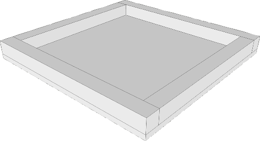
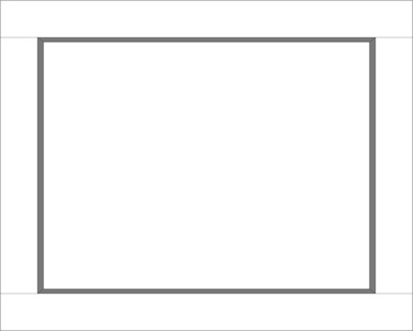
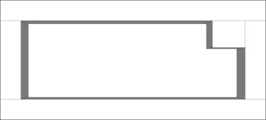
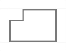
Bottom slab
550x550x50 mm
7 concrete blocks 550x170x60 mm
1 concrete block 480x170x60 mm with notch 70x58 mm
5 concrete blocks 410x170x60 mm
1 concrete block 246x170x60 mm with notch 70x58 mm
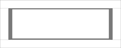
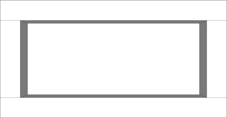
Moulds 24 mm of height
1 concrete block 550x170x60 mm with ledge to hold the partition (100x27x8 mm)
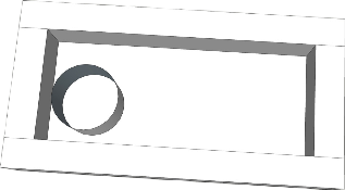
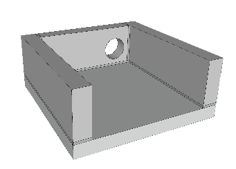
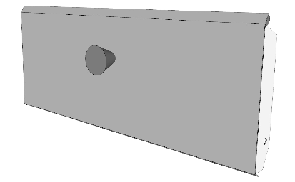
1 concrete block 410x170x60 mm with Ø 100 mm opening for flue pipe (18 mm from the sides)

Lintel that comes above of the firebox 364x48x60 mm
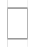
Partition 402x305x24 mm
Trapdoor 187x120x24 mm

1 concrete block 170x98x60 mm with notch 28x15 mm (joining block)
Step 3 Refractory concrete castings
What’s new: the 2019 model has a floor channel instead of a p-channel, and concrete castings replace the Portuguese bricks (that are only available in Portugal).
Working with fire concrete is very different from working with normal concrete. Things like temperature, amount of water to be added and the open time for handling come very exact. Mixing and vibrating are skills to be learned by experience; if you do this for the first time consider your first castings to be try-outs.
Temperature
To process the material well, the concrete as well as the water to be added need to have a temperature between 10 - 20º Celsius. The very minimum is 7ºC. Exceeding 20ºC the hardening process will be substantially faster. There may be too little time then to process the mixture well.
Water
Use good quality drinking water of 10º - 20º C temperature. From the product information sheet, calculate the exact amount of water to be added. Note that this can be very different per product! E.g. for CaldeCast StrongLite you need ±225 ml/kg, but for Calderys F50 it's only 115 ml/kg. Do not exceed the maximum amount as indicated on the product sheet.
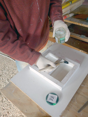
Mould
Before putting the concrete into the mould, the inside of the mould needs to be thoroughly greased with oil, otherwise the concrete would be fixed to the mould after hardening.
Mixing
Definitely use a dust mask to prevent breathing cement dust. Generally the concrete is shipped in sacs as a dry mix, needing only water to be added. Weigh the amount of concrete you need and put it in a bowl. Add the measured amount of water and mix thoroughly with a trowel. Mixing time shouldn't exceed 3 minutes. You now have an earth-humid material that immediately needs to be shoveled into the mould.
Applying
Fill up the mould and switch on the vibration table's motor. After some minutes of shaking the concrete will get more fluid and air bubbles will move out. With a filling-knife, push the concrete into the corners. If needed, add more concrete into the mould. Vibrating time shouldn't be too short, but certainly not too long: that would cause demixing. Water on top of the mixture is an indication of demixing. This should be prevented.
Hardening
The concrete hardens by a chemical reaction between the aluminium cement and the water. This may produce heat. Directly after vibrating, cover the mould with a piece of plastic to prevent evaporation of the water. At 15 - 20ºC, hardening will take about 6 -8 hours. 80% of its strength is then attained (after ± 2 weeks the concrete has fully completed hardening). At lower temperatures of working space and/or material hardening will take longer. Before de-moulding check if the concrete has hardened well. To de-mould, take off one side of the mould and tap the form out.
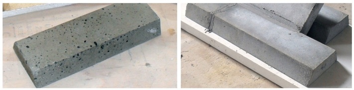
too much airbubbles
this is okay
Mould dimensions
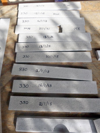
Riser bricks (insulating refractory concrete). Height of mould: 15 mm. You can make a seperate mould for the 330 mm bricks, or use only this mould and grind off 20 mm from 7 castings.
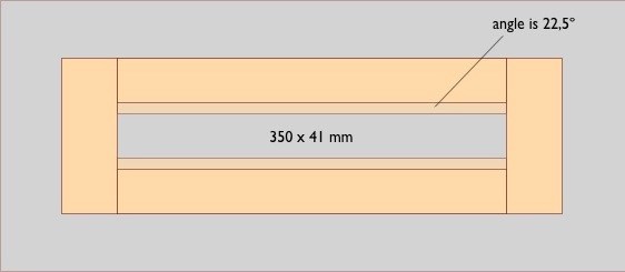
Heel (insulating refractory concrete). Height of mould: 24 mm. After hardening, the heel is adjusted with a grinder to make it fit in the riser.


220 x 160 mm
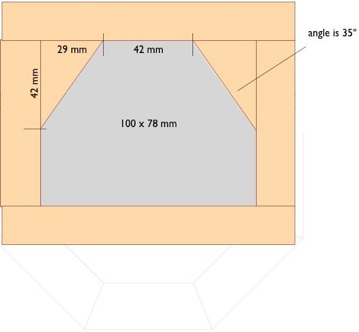
Top of firebox (solid refractory concrete). Height of mould: 30 mm


90 x 159 mm
Port (solid refractory concrete). Height of moulds: 30 mm


90 x 159 mm


220 x 91 mm
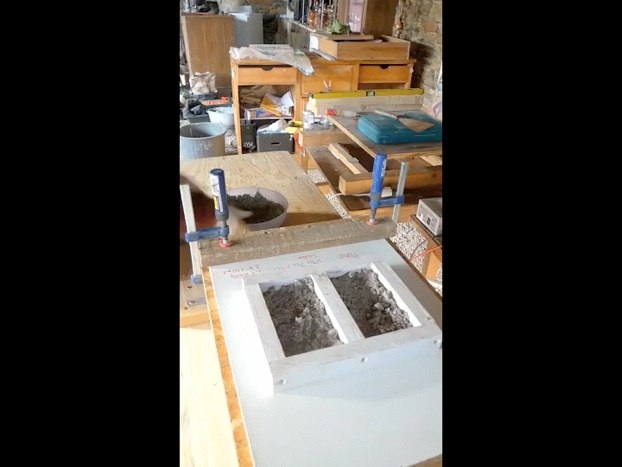
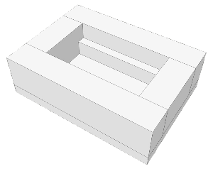
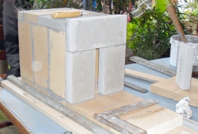
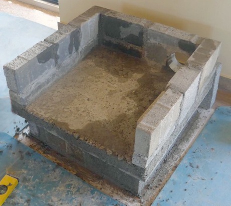
Step 4 Making the lower section of the bell and the core’s firebox
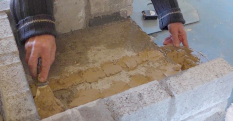
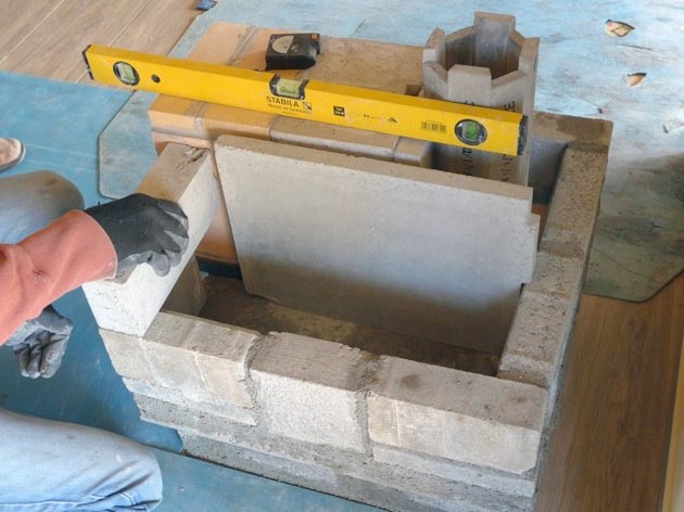
Place the cast bottom slab in a suitable place for working. It must be level. Construct the first layer of concrete blocks on the bottom slab. Use mortar with cement : sand in proportions 1:5. Take care to control the dimensions (height is 170 mm + 10 mm joint) and make sure the structure is square and level.
This lower part of the bell is now ready for transport to the site.
Making the firebox
This building description assumes that the core is built off-site for transport to the final installation location. The core is built up on a transport board that must be sturdy enough to carry its weight. A sheet of 18 mm melamine-coated chipboard or similar works well.
Place a pair of battens parallel on the transport board and lay a couple of the bottom firebricks in place between them to get the correct spacing. Fix the battens lengthwise on the transport board. This structure will hold the bottom firebricks in place during the build.
Construction work is easiest if the transport board can be placed on a workbench or raised to a similar height.
(An alternative method is to construct the core in-situ on top of the bottom slab.)
About glueing with Moviset
Spread the glue over the surfaces to be glued: both surfaces need to be covered completely (not thick, only ± 0,5 mm). There must be no air spaces when the surfaces come together.
Moviset sets within 24 hours when the temperature is 15°C or above. At lower temperatures, setting time is not yet known, but it may be much slower.
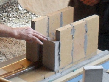
Bottom firebricks and firebox
This building description assumes firebricks with measurements 220 x 110 x 30 mm, and for the bottom of the core 220 x 110 x 50 mm. For the bottom you need four full firebricks and one cut firebrick.
Exactly in the middle of 3 (full) bottom bricks, you cut out a notch of 40 x 20 mm. This will form the slot that accepts the floor channel.
Butter one edge of the first firebrick with Moviset and lay it on the transport board. Butter two edges of the next three bricks and lay them in place. Carefully apply pressure across the four firebricks until the Moviset begins to squeeze out. A large clamp helps with the application of a little pressure. Now measure for cutting of the fifth firebrick; the total length of the core base must be 506 mm. Cut the final brick to achieve this total length (remembering to take account of the 1 mm of Moviset). Make sure the bottom bricks are level and let dry for a short time.
Glue the walls of the core onto the base: three firebricks placed vertically for the left, three for the right side. Try to make sure the firebricks that will be visible at the front of the core are all flush; this is simply an aesthetic consideration. Allow to harden for a short time.
Next form the port at the rear of the core. Glue the two vertical port castings and then the lintel casting across the top. Careful measurement is necessary here. Most important is that all of the rear port castings are perfectly vertical and aligned so that they form a flush surface (for later installation of the riser). The top of the port lintel should be level. The port opening must be 40 mm wide.


1. Transport board
2. Floor bricks
3. Walls, port bricks
4. Upper port brick
5. Top bricks
6. 45º bottom bricks

4 mm space

Finally, glue on the firebox top, which consists of one casting, one whole firebrick, and one firebrick cut to size such that the front of the firebox is flush. The part-firebrick goes at the front with cut face inwards to ensure that top joints are offset from the wall joints (for added strength) and to preserve the aesthetics of the front. (Remember that the front edge of the firebox is visible to the end user when the Roquetinho door is opened.)
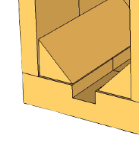
The 45º chamfered bottom bricks can then be glued into the firebox, ensuring that all gaps are filled with Moviset. Leave open a space of 4 mm between the bottom bricks and the front of the firebox. This is where the floorchannel’s frontplate will fit in.
The 3D Sketchup file for the core is in the Roquetinho-folder.
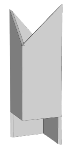
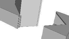
Step 5 Lower part of the riser and assembling the core


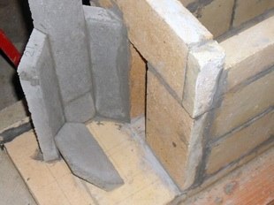
Each of these cut riser castings can then be glued with Moviset to two others using a 135° lath to set the correct angle (as shown in the picture). Leave these assemblies to harden for a while, then glue them to the firebox port. The tops of the cut riser castings must be flush with the top of the firebox port lintel. Now, before closing the riser with the final casting, the heel must be fixed in place at the bottom of the riser with some glue, filling up (completely!) the space underneath it with cob or glue. Ensure the correct position/angle by inserting a lath cut with a 45° end into the port through the firebox. Now close the back of the riser with the final riser casting using Moviset.
Now leave the core assembly to set hard before transporting it to site. At this point you can already glue the upper riser together. Like the bottom part, half of the castings are 350 mm of length, the other half 330 mm. Making it this way, the upper part will fit exactly in the bottom part.
Also you can already glue together the firebricks for the upper bell (see Step 9).
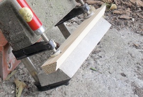
grind in an angle of 45º
First cut two bricks the same height as the port,
then grind them in an angle of 45º.
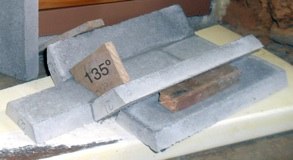


... then glue the heel.
Glue these castings together, using a 135º lath (picture) ...
... then glue them on the bottom and onto the firebox port ...


... and the 3 short sections
(glue joint at the bottom is 1 mm)
Finally, glue in the back riser casting...


Step 6 Metalwork: floor channel, frame and door unit, top plate
A --- A, seen from above
233 x 308
313


258


A
A


3
6
2 henges
± 8 x 40 mm


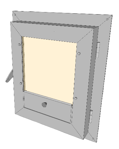
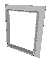
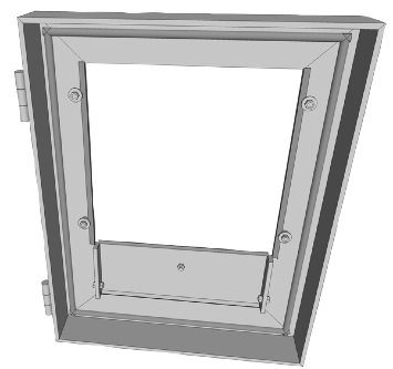
Frame
Door
Take the door apart. Drill holes in it for the bolds that hold the glass. Before placing the glass window, put a stripe of refractory sealant at the left- and right side (not at the top). Place the window on the two bars and press it into the sealant. Put in the bolds, nuts and rings that keep the window on its place.
The chink at the top of the window is to have just a bit of air coming in to keep the window clean.
Now glue fire cord at the inside of the door, exactly where it meets the frame (remember that the space between frame and door at the left side is 6 mm, and for the rest 3 mm).
The dimensions of the floor channel and the frame and door unit assume a core with outside dimensions of
220 x 301 x 506 mm. If these dimensions differ you need to adapt the blue figures in the pictures.
The 3D Sketchup files for the floorchannel and the frame&door unit are in the Roquetinho-folder.
Making the frame and door
Cut the pieces for the frame and the door out of 40 x 40 x 4 mm L-profile. First weld the frame, then the door. Drill 4 holes in the corners of the frame, in such a way the screws (that fix the frame to the stove) will get in the middle of the lintel / bottom slab as much as possible.
Make two 66 x 12 x 4 mm bars, these are to support the glass window. Drill a hole in the bars, where the vent is going to be attached. Weld the bars at the inside of the door.
Weld the 2 henges to the frame and to the door, making sure that at the top, the bottom and at the right side the space between door and frame is 3 mm, and at the left side 6 mm.


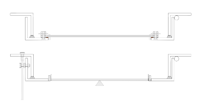
Making the floor channel
Out of 40 x 20 x 1,5 mm profile, cut a piece of 306 mm and one of 24 mm and cut out the triangles for the 25 x 25 tube to fit in.
Out of 25 x 25 x 1,5 mm profile, you cut a piece of 85 mm. From two sides at the bottom, take out 17 mm. From the upper 25 mm you take out triangles (see picture).
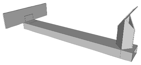


Weld the parts together. Mind that where the sides of the 25 x 25 tube meet the 40 x 20 pipe there's 2 chinks that need to be tightened.
Cut two triangles from a 53 x 35 mm plate and weld it onto the 25 x 25 pipe. Now fit the channel in the firebox to make sure the dimensions are okay, then add the 158 x 43 mm front plate. This front plate fits in the two 4 mm notches in front of the corner bricks.


306


24


small strip to tighten the chink
Vent
Make the vent out of a piece of 0,5 mm thick steel. Drill holes in the side that correspond with the holes in the two bars. Attach the cord at the top, and the cupboard knob. Attach the vent to the door with bolds and nuts; tighten it just as much it's not too tight or too loose when you open it.


4,5
fire cord


12


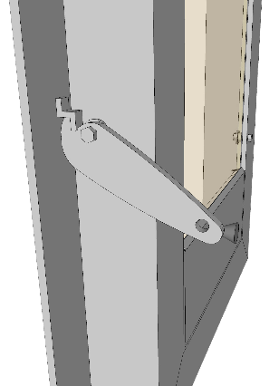
Lock
In a steel plate of 75 x 25 x 4 mm you drill holes as indicated on the picture. Then you cut it with a small grinder and smoothen the edges with a file. On the exact spot on the door, you drill a hole and fix a bold in it on which you attach the lock. A strip of steel is welded to the frame to accept the grip of the lock.


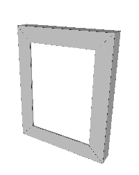
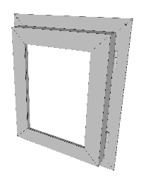
Top frame and top plate
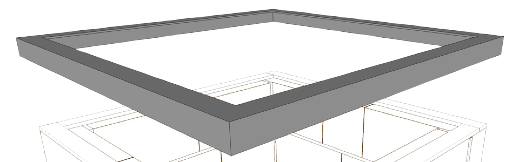
Steel top frame
At the top of the bell comes a frame made out of 30 x 30 x 3 mm L-profile, to improve solidity of the bell. The gap between the top and the frame is only 1 mm, so it needs to be welded with care. Dimensions are 558 x 558 mm at the outside, the square opening at the inside is 498 x 498 mm.
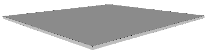
Top plate
The top of the bell is an 8 mm steel plate with dimensions 490 x 490 mm.
refractory sealant


fire cord


2 bars that support the window 66x12x4


4,5


bar 66x12x4
cord
ring
2 nuts 3 mm high for distance
glass 185 x 185 x 4 mm
bar
vent 0,5 mm steel
bar


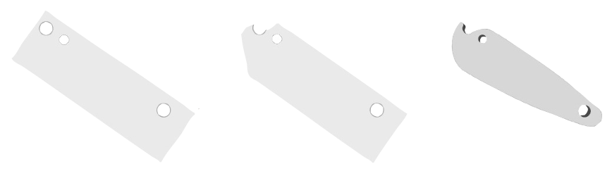

plate 53x35
Step 7 On-site: plinth, lower section of the bell, installing the core
Once on site, determine the location of the Roquetinho. The rear edge of the bottom slab should be placed at least 160 mm from the rear wall (to allow space for connecting the flue). Mark the footprint of the plinth on the floor according to the chosen overhang. Note well when aligning the plinth that the flue does not exit in the centre of the Roquetinho. The floor can be protected by sticking lengths of masking tape 10 mm outside this footprint.
Construct the plinth using concrete blocks and normal mortar. Ensure it is square and level. Butter the top face of the plinth with an even layer of mortar and lower the bottom slab onto it. Positioning is made easier if two concrete blocks (standing on end) are placed on the floor so as to mark the locations of the two rear corners. Tap the bottom slab down gently so that it settles into place firmly (and level) on the mortar.
Installing the core
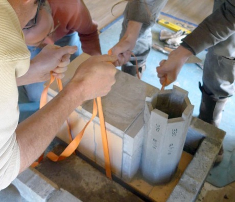
Remove the battens from the transport board. Carefully slide a pair of lightweight winching straps under the core to use as lifting handles; this is best done by sliding the core slightly off the end of the transport board and lifting it up a few degrees, making sure to take the weight on the middle of the bottom.
Use a few concrete blocks to form a platform in front of the bottom slab. Lift the core, still on the transport board, onto this platform. Ideally the core will now be at almost its installed height.
Prepare some cob and spread it in three lines 3 mm thick from front to back of the bottom slab where the core will be placed. The two outer lines will go under the sides. When the core is settled onto this cob, it will spread slightly. It is important that there are no sealed air pockets; air should be able to escape forward between the lines of cob.
Gently lift the core using the straps. Two people are needed to do this, with a third to ensure proper positioning of the core on the bottom slab. Lower the core such that there is a gap of 12 mm to the left wall of the bell; this space will be filled with superwool. The front of the core protrudes exactly 30 mm in front of the bottom slab.
Ensure that the core settles into place level and without going out of position. It can be tapped gently with a rubber mallet. Fill the 12 mm gap with superwool. At the front it needs to be as airtight as possible.
Step 8 Lower bell construction, upper part of riser, insulating the riser
Lower bell construction
Second layer, partition and trapdoor opening
Now lay the joining concrete block with mortar (1:5). The 27 x 15 mm notch holds the front of the partition. Press the joining block firmly against the superwool and use a pressure lath to keep it in place.
Lay the second layer of concrete blocks using cob, except for the trapdoor lintel: lay that one with mortar.
The left side block and the trapdoor lintel have notches that need to be flush with the top of the firebox.
The concrete block with the ledge must be laid accurately at the back; the upper back of the partition is now held in place by it.
Floorchannel and door lintel
Drop the floorchannel into place. If good, it will fit easily in the slot, and the front plate will fit in the 4 mm space at the front of the firebox.
Place a piece of superwool measuring 330 x 242 mm over the whole firebox. Put the door lintel in place with cob and press it firmly into the superwool: the joint between the firebox and the lintel must be airtight.
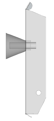
Insulating the riser
Insulating lower riser with vermiculite
Upper riser and fracture point
The upper part of the riser can now be placed onto the bottom part. Use a small amount of clay between the upper and lower parts instead of glue, creating a fracture point. Because of the extreme temperatures, the two parts will expand at slightly different rates, and this fracture point prevents the upper part of the riser from cracking.
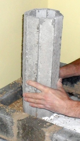
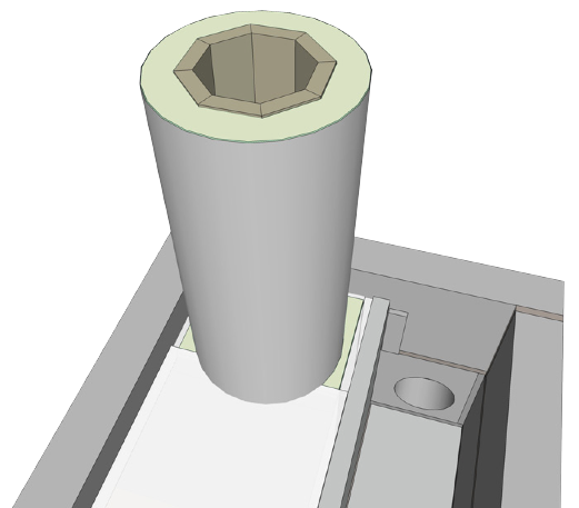
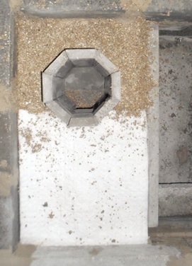
Insulating the upper riser
Lower the 200 mm diameter steel tube over the riser until it rests on the firebox top and the vermiculite fill.


fracture
joining block 170x98x60

partition 402x305x24

ledge 100x27x8

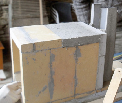
Step 9 Upper bell construction, steel top, frame & door unit
Upper bell construction
Building up the rest of the bell it is best to have some kind of guides. One method is to clamp laths to the four corners at the bottom slab; mark them with the layer heights (which are height of the concrete blocks + 10 mm joint for layers 3 and 4, and height of the firebricks + 7 mm joint for layers 5 to 8). Use spacers to bring the laths 2 mm away from the bell and level the laths carefully. String can be used between the laths to get each layer exactly level.
Lay the concrete blocks for layers 3 and 4 using cob.
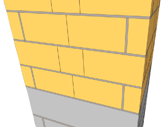
From the 5th layer you use the firebricks. Before starting to lay these, you glue the vertical joints of the bricks that come in the middle, using Moviset, and let it harden for a day. Only at the corners you use cob for the vertical joints. This way, it’s easier to repair whenever there are cracks in the upper bell, once you use the stove. A crack is repaired by making the cob wet again and push some new cob into the joint.
Lay the firebricks for layers 5 to 8 using cob; the horizontal joints here are 7 mm.
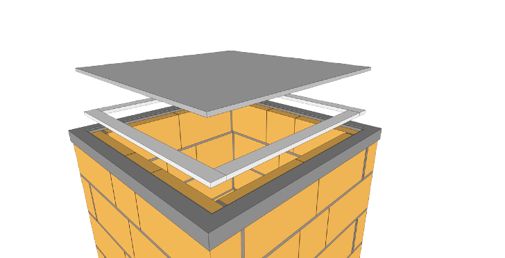
The top frame
Lay the steel frame over the bell’s top using cob. Carefully check the
1 mm margins at the sides. Remove the cob that squeezes out. Height (cob + steel) should be ± 10 mm.
The steel top
Now lay 4 strips of superwool on top of the bricks, and place the steel plate. There’s a margin of 4 mm at the sides between the plate and the frame.
glue

cob


Placing the frame & door unit
Take the frame and fit it over he protruding front of the firebox. Outline the exact places on the stove and drill holes for the plugs and screws. Fix the frame and attach the door to it.
Trapdoor
One last thing: placing the trapdoor. Once a year it might be useful to cut it open and clean the inside of the stove. Fix it (airtight!) with sealant.
© 2018 roquetinho.eu
© 2019 roquetinho.eu. This building description is available under the Creative Commons Attribution-ShareAlike 4.0 International license.
